Framing details are necessary with almost any building structural system in use today. Straw bale buildings must have structural support members for load-bearing walls and roof assemblies, rammed earth buildings need structural framing for door and window openings, and of course, wood-framed homes need lots of details for structure and weatherproofing assemblies.
Design details provide templates for structural stability to keep the roof on the building (very important!), especially during high- risk events like snow storms or tornados. Wall assemblies also keep air infiltration manageable, help keep rain-driven water out of the wall assembly and allow moisture and water vapor that does get inside the wall to dry out. These details will vary depending on the climate location that the home is built in.
Your home plans should include framing details for every build- ing section, as well as detailed assembly specifications for walls, foundation, roof members and water flashing details for roofs, walls, windows and doors. The basic principles related to the building envelope are more influenced by design than the materials themselves, so they are best addressed here. By providing framing details in the drawings, framing contractors onsite are less likely to over-build assemblies, thinking that it is better to err on the side of adding more lumber than is necessary for structural integrity than not enough. Do not assume that the education level of a framing crew provides expertise in structural engineering or waterproofing. Instead, have your structural engineer or architect provide the framing and waterproofing details for wall, roof and floor assemblies (if you are not using engineered trusses or panelized assemblies). This will save you money because every material you purchase will be used as it was intended, instead of being mis- used, requiring you to purchase more materials either during construction or to repair poor workmanship later. O en construction drawings give the crew no clue as to how to waterproof and ash the critical openings and junctions in the house where most leaks will occur. A recent article in Builder Magazine8 found that about one-third of US homebuilders still don’t properly ash windows to prevent direct intrusion by rain. It stated that water leaks, especially around windows due to improper flashing, “routinely tops the list of builder callbacks.” It is imperative to the durability of your home that the flashing materials and their installation be detailed on the drawings.
Good building science is the perfect partner to green materials and design. Using the right materials to create the right building system for your climate will maximize the durability, healthfulness, comfort and efficiency of your new home. Make certain that your architect or engineer is on-board with your desire to maximize structural integrity while reducing waste and achieving a water- tight, durable and healthy structure.
If you have hired a custom builder for your project and are not working with the architect directly, you should make certain that the home plans that the builder is offering you have been designed according to the strategies outlined in this chapter to ensure that construction will be resource efficient. You should also ask the builder for written specifications for the basic building materials that are included in his quote for the home. Better to find out up- front if there are any surprises coming down that will throw you o budget.
Framing Details
Thursday, October 26, 2017Selecting a site that has good solar orientation
Wednesday, October 25, 2017
Selecting a site that has good solar orientation is one of the best strategies to lower your home’s operating costs. To determine the best way to orient your house based on this sun path, you need to figure out where you are on the planet. In the northern hemisphere, the sun is never in the northern sky, and it is either high in the sky (in the summer) or low toward the southern horizon (in the winter).
We’ll take a rectangular box design to illustrate the best design for passive solar benefits. To achieve the best orientation of your home on the site, you’ll need to determine the sun path across the site, from east to west. Once you have charted the sun paths, you will need to determine if it is possible to design the home on the site with the long walls of the rectangle running east to west (“east- west axis”).
It is important to recognize that the correct orientation of your house isn’t limited to which side of it faces the street. Which walls are the long or short walls will depend on how you design the home for the site. is could mean the front is a long wall if your site is facing south, or if your lot faces west, it could mean that the side wall facing south is now the focal point of a courtyard. Or maybe the house faces north and the back patio has large overhangs that serve as a passive solar feature. But if the site is on the north slope of a hill, having good solar orientation for your home is going to be a concern. e point is to make the best use of your site by designing for it.
Vapour barrier: Vapour check, External insulation, Resistance to the passage of sound.
Sunday, February 6, 2011The moisture vapour pressure from warm moist air inside insulated buildings may find its way through internal linings and condense to water on cold outer faces. Where the condensation moisture is absorbed by the insulation it will reduce the efficiency of the insulation and where condensation saturates battens, they may rot.
Insulating materials by themselves do not provide a satisfactory external finish to walls against rain penetration or for appearance sake and have to be covered with a finish of cement rendering, paint or a cladding material such as tile, slate or weatherboarding. For rendered finishes, one of the inorganic insulants, rockwool or cellular glass in the form of rigid boards, is most suited. For cladding, one of the organic insulants such as XPS, PIR or PUR is used because their low U values necessitate least thickness of board.
As a base for applied rendering the insulation boards or slabs are first bedded and fixed in line on dabs of either gap filling organic adhesive or dabs of polymer emulsion mortar and secured with corrosion resistant fixings to the wall. As a key for the render coats, either the insulation boards have a keyed surface or expanded metal lath or glass fibre mesh is applied to the face of the insulation. The weather protective render is applied in two coats by traditional wet render application, by rough casting or by spray application and finished smooth, coarse or textured. Coarse, spatter dash or textured finishes are preferred as they disguise hair cracks that are due to drying shrinkage of the rendering.
Because the rendering is applied over a layer of insulation it will be subject to greater temperature fluctuations than it would be if applied directly to a wall, and so is more liable to crack. To minimise cracking due to temperature change and moisture movements, the rendering should be reinforced with a mesh securely fixed to the wall, and movement joints should be formed at not more than 6 m intervals. The use of a light coloured finish and rendering incorporating a polymer emulsion will reduce cracking.
As the overall thickness of the external insulation and rendering is too great to be returned into the reveals of existing openings it is usual to return the rendering by itself, or fix some non-ferrous or plastic trim to mask the edge of the insulation and rendering. The reveals of openings will act as thermal bridges to make the inside face of the wall around openings colder than the rest of the wall. Figure 106 is an illustration of insulated rendering applied externally.
Tile and slate hanging, timber weatherboarding and profiled sheets can be fixed over a layer of insulating material behind the battens or sheeting rails to which these cladding materials are fixed.
Slabs of compressed rockwool are cut and shaped with bevel edges to simulate the appearance of masonry blocks. The blocks are secured to the external face of the wall with stainless steel brackets, fixed to the wall to support and restrain the blocks that are arranged with either horizontal, bonded joints or vertical and horizontal continuous joints. An exterior quality paint is then applied to the impregnated surface of the blocks. At openings, non-ferrous or plastic trim is fixed around outer reveals.
Details of insulating materials are given in Table 7.

The requirement of Part E of Schedule 1 to the Building Regulations is that walls which separate a dwelling from another building or from another dwelling shall have reasonable resistance to airborne sound.
Where solid walls of brick or block are used to separate dwellings the reduction of airborne sound between dwellings depends mainly on the weight of the wall and its thickness. A cavity wall with two leaves of brick or block does not afford the same sound reduction as a solid wall of the same equivalent thickness because the stiffness of the two separate leaves is less than that of the solid wail and in consequence is more readily set into vibration.
The joints between bricks or blocks should be solidly filled with mortar and joints between the top of a wall and ceilings should be filled against airborne sound transmission.

Mortar for brickwork and blockwork.
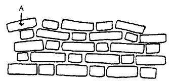
Monday, January 10, 2011Because of the variations in shape and size, the courses of bricks would not lie anywhere near horizontal. One of the functions of brickwork is to support floors and if a floor timber were to bear on the brick marked A it would tend to cause it to slide down the slope on which it would be resting. It is essential, therefore, that brickwork be laid in true horizontal courses, and the only way this can be done with bricks of differing shapes and sizes is to lay them on some material which is sufficiently plastic, while the bricks are being laid, to take up the difference in size, and which must be able to harden to such an extent that it can carry the weight normally carried by brickwork.
The material used is termed mortar. The basic requirements of a mortar are that it will harden to such an extent that it can carry the weight normally carried by bricks, without crushing, and that it be sufficiently plastic when laid to take the varying sizes of bricks, It must have a porosity similar to that of the bricks and it must not deteriorate due to the weathering action of rain or frost.
Sand is a natural material which is reasonably cheap and which, if mixed with water, can be made plastic, yet which has very good strength in resisting crushing. Its grains are also virtually impervious to the action of rain and frost. The material required to bind the grains of sand together into a solid mass is termed the matrix and the two materials used for this purpose are lime or cement.
Ventilation - comfort and good health in buildings.
Wednesday, January 5, 2011For comfort and good health in buildings it is necessary to provide means of ventilation through air changes through windows or yentilators, that. can be controlled, depending on wind speed and direction and outside air temperature, to avoid the sensation of ‘stuffiness’ or cold associated with too infrequent or too frequent air changes respectively. As with heating, the sensation of stuffiness is highly subjective.
Calculation Methods for the SAP for dwellings.
(1) an elemental method
(2) a target U value method
(3) an energy rating method.
In the elemental method standard U values for the exposed elements of the fabric of buildings are shown under two headings: (a) for dwellings with SAP ratings of 60 or less and (b) for those with SAP ratings over 60. The standard U values are 0.2 and 0.25 W/m2K for roofs, 0.45 W/m2K for exposed walls, 0.35 and 0.45 W/m2K for exposed floors and ground floors, 0.6 W/m2K for semi-exposed walls and floors and 3.0 and 3.3 W/m2K for windows, doors and rooflights, the two values being for headings (a) and (b), respectively. The basic allowance for the area of windows, doors and rooflights together is 225% of the total floor area. The area of windows, doors and rooflights, larger than those indicated by the percentage value, may be used providing there is a compensating improvement in the average U value by the use of glazing with a lower U value.
The target U value method for dwellings is used to meet the requirement for conservation of fuel and power by relating a calculated average U value to a target U value, which it should not exceed. The average U value is the ratio of:

The total area of exposed floors, windows, doors, walls and roof and the standard U values in the elemental method are used to calculate the heat loss per degree. Where the calculated average U value exceeds the target U value it is necessary to improve the thermal resistance of walls, windows or roof either separately or together so that the average U value does not exceed the target U value. As an option, account may be taken of solar heat gains other than those allowed for in the equation on which the method is based. This method is based on the assumption of a boiler with an efficiency of at least 72%. Where a boiler with an efficiency of 85% is used the target U value may be increased by 10%. The use of the elemental or target U value methods of showing compliance does not give exemption from the requirement to give notice of an SAP rating.
The energy rating method is a calculation based on SAP which allows the use of any valid conservation measures. The calculation takes account of ventilation rate, fabric losses, water heating requirements and internal and solar heat gains.
The requirement for conservation of fuel and power will be met if the SAP energy rating for the dwelling, or each dwelling in a block of flats or converted building, is related to the floor area of the dwelling and ranges from 80 for dwellings with a floor area of 80 m2 or less to 85 for dwellings with a floor area of more than 120 m2.
As there is a requirement to complete the SAP worksheet to determine an SAP rating, which has to be notified to the local authority, whichever method of showing compliance is used the most practical and economic method of approach is to use the standard U values for SAP ratings over 60 set out in the elemental method in the initial stages of design, and then to complete the SAP worksheet at a later stage and make adjustments to the envelope insulation, windows and boiler efficiency as is thought sensible to achieve a high SAP rating.
Consevation of fuel and Power Standard assessment precedure (SAP) rating
The SAP rating is based on an energy cost factor on a scale of 1 to 100, 1 being a maximum and 100 a minimum energy use to maintain a comfortable internal temperature and use of energy in water heating. While there is no obligation to achieve a particular rating, a rating of 60 or less indicates that there is inadequate insulation or inefficient heating systems or both, and the dwelling does not comply with the regulations.
Details of the notification of the SAP rating for new dwellings are held by the local authority. A prospective purchaser of the dwelling may well be put off where the rating is 60 or less and the local authority has not issued a Certificate of Compliance with the Regulations, whereas the purchaser will be encouraged by a rating of say 85, which shows compliance with the Regulations.
The SAP rating is calculated by the completion of a four page worksheet by reference to 14 tables. The sequential completion of up to 99 entries by reference to the 14 tables is so tedious and difficult to follow as to confound all but those initiated in their use, and is hardly calculated to inform householders in a way that is simple and easy to understand as claimed by the authors of Approval Document L.
Damp-proof courses in cavity walls.
Sunday, January 2, 2011Where the dpcs in both leaves of a cavity wall are at least 150 mm above outside ground level and the floor level is at, or just above, ground level, it is necessary to dress the dpm up the wall and into the level of the dpc. This is a laborious operation which makes it difficult to make a moisture tight joint at angles and intersections.
The solution is to lay the dpc in the inner leaf of the cavity wall, level with the dpm in the floor, as illustrated in Fig. 37.
Where the level of the foundation is near the surface, as with trench fill systems, it may be convenient to build two courses of solid brickwork up to ground level on which the cavity wall is raised, as illustrated in Fig. 38. As little vegetable top soil has been removed the floor level finishes some way above ground and the dpm in the floor can be united with the dpc at the same level.
The cavity insulation is taken down to the base of the cavity to continue wall insulation down to serve in part as edge insulation to the floor construction.
It is accepted practice to finish the cavity in external walling at the level of the dpc, at least 150 mm above ground, where the wall is built as a solid wall up to the dpc, as illustrated in Fig. 38. This form of construction may be used where the inner leaf of the cavity wall was built with light weight concrete blocks, used for their insulating property. These blocks fairly readily absorb moisture, expand when wet and might be affected by frost and deteriorate, whereas solid brickwork below ground will provide a stable base.
With this arrangement the requirements of the Building Regulations recommend the use of a cavity tray at the bottom of the cavity. This tray takes the form of a sheet of a flexible, impermeable material such as one of the flexible dpc materials which is laid across the cavity from a level higher in the inner leaf so that it falls towards the outer leaf to catch and drain any snow or moisture that might enter the cavity. The cavity thus acts as both tray and dpc to the cavity wall leaves.
In this detail of construction the under concrete insulation is below the lowest level of the cavity and should be turned up against the outer walls as edge insulation.


Brick damp-proof courses.
Beca use of the dissimilar colour and texture of these bricks to that of facing bricks and the cost of the material this form of dpc is little used.
Slate damp-proof courses.
Two courses of dense Welsh slates were laid at first in lime or hydraulic Iimc and sand, and later in cement and sand. The slates were laid on a bed of mortar in two courses, breaking joint as illustrated in Fig. 36. Because of the small units of slate and the joints being staggered this dpc could remain reasonably effective where moderate settlement occurred.
To be effective the edges of the slates should be exposed on a wall face and not be covered, which made a deep, somewhat ugly joint.
The majority of external brick walls are built as a cavity today and it would be laborious, wasteful and therefore expensive to use a separate slate dpc in each leaf of the wall.

Rigid damp-proof courses.
Damp-proof courses above ground.
Saturday, December 25, 2010There should be a continuous horizontal dpc above ground in walls whose foundations are in contact with the ground, to prevent moisture from the ground rising through the foundation to the wall above ground, which otherwise would make wall surfaces damp and damage wall finishes. The dpc above ground should be continuous for the whole length and thickness of the wall and be at least 150 mm above finished ground level to avoid the possibility of a build up of material against the wall acting as a bridge for moisture from the ground as illustrated in Fig. 35.

Damp-proof courses.
One of the functional requirements of walls (see C.hapter 2) is resistance to moisture. A requirement of the Building Regulations is that walls shall adequately resist the passage of moisture to the inside of the building. To meet this requirement it is necessary to form a barrier to moisture rising from the ground in walls. This barrier is the horizontal, above ground, dpc.
Resistance to the Passage of Heat.
Of the heat that is transferred through a solid, ground supported floor a significant part of the transfer occurs around the perimeter of the floor to the ground below, foundation walls and ground around the edges of the floor, so that the cost of insulating the whole floor is seldom justified. Insulation around or under the edges of a solid floor will significantly reduce heat losses to the extent that overall insulation is unnecessary.
In the CIBS guide to the thermal properties of building structures, the U value of an uninsulated solid floor 20 x 20 m on plan, with four edges exposed, is given as 0.36 W/m^2K and one 10 x lOm as 0.6 W/m2K. The 20 x 20 floor has a U value below that in the requirement of the Building Regulations and will not require insulation. The U value of a 10m2 floor can be reduced by the use of edge insulation. With edge insulation of a metre deep all around and under the floor, the U value can be reduced to 0.48 W/m^2K which is somewhat higher than the U value in the requirement of the Building Regulations and may necessitate some small overall insulation. This is the basis for the assumption that floor slabs that are larger than 10 m in both length and width may not need an overall insulation layer.
To reduce heat losses through thermal bridges around the edges of solid floors that do not need overall insulation, and so minimise problems of condensation and mould growth, it may be wise to build in edge insulation, particularly where the waIl insulation is not carried down below the ground floor slab. Edge insulation is formed either as a vertical strip between the edge of the slab and the wall or under the slab around the edges of the floor as illustrated in Fig. 32. The depth or width of the strips of insulation vary from 0.25 m to 1 m and the thickness of the insulation will be similar to that needed for overall insulation.
The only practical way of improving the insulation of a solid ground floor to the required U value is to add a layer of some material with a high insulation value to the floor. The layer of insulation may be laid below a chipboard or plywood panel floor finish or below a timber boarded finish or below the screed finish to a floor or under the concrete floor slab, With insulation under the screed or slab it is important that the density of the insulation board is sufficient to support the load of the floor itself and imposed loads on the floor. A density of at least 16 kg/rn^3 is recommended for domestic buildings.
The advantage of laying the insulation below the floor slab is that the high density slab, which warms and cools slowly (slow thermal response) in response to changes in temperature of the constant low output heating systems, will not lose heat to the ground. The damp- proof membrane may be laid under or over the insulation layer or under the floor screed. The damp-proof membrane should be under insulation that absorbs water and may be over insulation with low water absorption and high resistance to ground contaminants.
With the insulation layer and the dpm below the concrete floor slab it is necessary to continue the dpm and insulation up vertically around the edges of the slab to unite with the dpc in walls as illustrated in Fig. 33.
One method of determining the required thickness of insulation is to use a thickness of insulation related to the U value of the chosen insulation material, as for example thicknesses of 25 mm for a U value of 0.02 W/m^2K, 37 mm for 0.03 W/m^2K, 49 mm for 0.04 W/m^2K and 60 mm for 0.05 W/m^2K, ignoring the inherent resistance of the floor.
Another more exacting method is to calculate the required thickness related to the actual size of the floor and its uninsulated U value, taken from a table in the CIBS guide to the thermal properties of building structures. For example, from the CIBS table the U value of a solid floor 10 x 6m, with four edges exposed is 0.74 W/m^2K.

These thicknesses are appreciably less than those given by the first method, shown in brackets.
Where the wall insulation is in the cavity or on the inside face of the wall it is necessary to avoid a cold bridge across the foundation wall and the edges of the slab, by fitting insulation around the edges of the slab or by continuing the insulation down inside the cavity, as illustrated in Fig. 34.
An advantage of fitting the dpm above the insulation is that it can be used to secure the upstand edge insulation in place while concrete is being placed.
The disadvantage of the dpm being below the concrete floor slab is that it will prevent the wet concrete drying out below and so lengthen the time required for it to adequately dry out, to up to 6 months. A concrete floor slab that has not been sufficiently dried out may adversely affect water sensitive floor finishes such as wood.
The advantage of laying the insulation layer under the screed is that it can be laid inside a sheltered building on a dried slab after the roof is finished and that the dpm, whether over or under the insulation layer, can more readily be joined to the dpc in walls, as illustrated in Fig. 34. Where the wall insulation is in the cavity it should be continued down below the floor slab to minimise the cold bridge across the wall to the screed as illustrated in Fig. 34.
If the dpm is laid below the insulation it is necessary to spread a separating layer over the insulation to prevent wet screed running into the joints between the insulation boards. The separating layer should be building paper or 500 gauge polythene sheet.
To avoid damage to the insulation layer and the dpm it is necessary to take care in tipping, spreading and compacting wet concrete or screed. Scaffold boards should be used for barrowing and tipping concrete and screed and a light mesh of chicken wire can be used over separating layers or dpms over insulation under screeds as added protection.


Drains - Natural system, Herring bone system, Grid system, Fan system.
Monday, December 6, 2010This system, which is commonly used for field drains, uses the natural contours of the ground to improve run off of surface ground water to spine drains in natural valleys that fall towards ditches or streams. The drains are laid in irregular patterns to follow the natural contours as illustrated in Fig. 19A.

Grid system.-

Fan system-
On sloping building sites on impervious soil where an existing system of land drains is already laid and where a new system is laid to prevent flooding a moat or cut off system is used around the new building to isolate it from general land drains, as illustrated in Fig. 21.
The moat or cut off system of drains is laid some distance from and around the new building to drain the ground between it and the new building and to carry water from the diverted land drains down the slope of the site. Plainly the moat drains should be clear of paved areas around the house.
Subsoil drains.
(1) to improve the stability of the ground
(2) to avoid surface flooding
(3) to alleviate or avoid dampness in basements
(4) to reduce humidity in the immediate vicinity of buildings.
Ground water, or land or field, drains are either open jointed or jointed, porous or perforated pipes of clayware, concrete, pitch fibre or plastic (see Volume 5). The pipes are laid in trenches to follow the fall of the ground, generally with branch drains discharging to a ditch, stream or drain.
On impervious subsoils, such as clay, it may be necessary to form a system of drains to improve the run off of surface water and drain subsoil to prevent flooding. Some of the drain systems used are natural, herring bone, grid, fan and moat or cut-off.
Site drainage.
Ground water is that water held in soils at and below the water table (which is the depth at which there is free water below the surface). The level of the water table will vary seasonally, being closest to the surface during rainy seasons and deeper during dry seasons when most evaporation to air occurs.
In Part C of the Building Regulations is a requirement for subsoil drainage, to avoid passage of ground moisture to the inside of a building or to avoid damage to the fabric of the building.
In Approved Document C to the Regulations are provisions for the need for subsoil drainage where the water table can rise to within 0.25 m of the lowest floor and where the water table is high in dry weather and the site of the building is surrounded by higher ground.
Paved areas are usually laid to falls to channels and gullies that drain to surface water drains.
Site preparation - Building.
Sunday, December 5, 2010Turf and vegetable top soil should be removed from the ground to be covered by a building, to a depth sufficient to prevent later growth. Tree and bush roots, that might encourage later growth, are grubbed up and any pockets of soft compressible material, that might affect the stability of the building, are removed. The reasons for removing this vegetable soil are firstly to prevent plants, shrubs or trees from attempting to grow under the concrete. In growing, even the smallest of plant life exerts considerable pressure, which would quite quickly rupture the concrete oversite. The second reason for removing the vegetable top soil is that it is generally soft and compressible and readily retains moisture which would cause concrete over it to be damp at all times. The depth of vegetable top soil varies and on some sites it may be necessary to remove 300 mm or more vegetable top soil.
In practice most of the vegetable top soil over a building site is effectively moved by excavations for foundations, levelling and drain and other service pipes to the extent that it may be necessary to remove top soil that remains within or around the confines of a building.